Chapter 7 - Mechanical Ventilation Systems
Chapter 7 - Mechanical Ventilation Systems
Fans are the heart of a mechanical ventilation system. Properly operating fans create an air pressure difference between the inside and outside. This air pressure difference, known as static pressure, causes the air flow that produces the air exchange required as part of a mechanically ventilated poultry house.
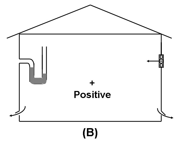
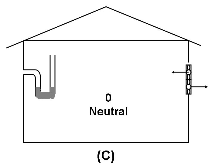
Figure 7.11 - Types of mechanical ventilation systems based on static pressure
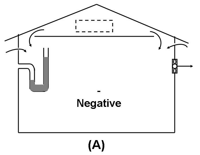
The most common system is shown graphically in Figure 7.11A. The exhaust fan(s) create a slight negative pressure or vacuum in the poultry house, which causes air to enter the barn through the designed inlets.
Positive pressure systems (Figure 7.11B) do the opposite. Fans blow air into the barn creating a positive pressure and air escapes through designed outlets. This system is fairly uncommon, since it often causes building materials to deteriorate because moisture moves through the cracks in the building.
A third system is a neutral pressure or push-pull system, shown in Figure 7.11C. Push-pull systems operate under neutral pressure at continuous or cold weather ventilating rates. A neutral pressure system has both an exhaust fan and an inlet fan, which create a zero or approximate neutral pressure difference between the inside and outside. Such a system typically becomes a negative pressure system when other larger exhaust fans operate during warmer weather.
Mechanical ventilation systems consist of four major components. They are: fans, openings, heaters, and controls. Fans and openings control the amount of air exchange in a mechanical ventilation system. The openings also have an impact on the air distribution and mixing in a mechanically ventilated poultry barn. Heaters provide supplemental heat to maintain desired indoor temperatures during cold weather and when chickens are too small or young to produce enough heat to keep the poultry house warm. Controls are needed to adjust ventilating rates (fan controls), supplemental heating rates, and the air velocity rates (fan controls), supplemental heating rates, and the air velocity through openings as weather, bird age and size change.
The term static pressure means the difference between the air pressure inside and outside the building. It is easy to measure this pressure - and knowing it is necessary when you select a fan and adjust inlets.
Static pressure is usually expressed as inches of water column (IWG). Static pressure or air pressure difference is usually measured between the inside and outside of a building with a manometer and is expressed in inches of water column (see Figure 7.12).
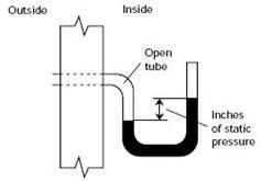
Figure 7.12 - Manometer used to determine building static pressure
Figure 7.12 shows a simple manometer, a section of clear plastic tubing partially full of water and bent into a 'U' shape. You can place this U-tube inside or outside the building. Note, however, that you always expose one end of the tube to the outside air pressure and the other to the inside conditions
.
Fans
Fans are used in mechanical ventilating systems to supply the energy needed to exchange the desired amount of air in a poultry house each minute. In a negative pressure system, fans are installed to exhaust stale or used air from the building and bring in fresh, clean air. It is very important to use only rated fans. Fan ratings are given in cubic feet of air per minute (CFM), or in SI units, cubic meters of air per hour, at specific static pressure levels.
Fan staging is an effective ventilation management tool. Single-speed fans can be staged to regulate ventilation airflow from minimum to maximum rates needed during the year. One or more fans can be used to provide the minimum required rate for winter moisture and ammonia control. As the outside temperature rises during mild weather, more fans are needed for both air exchange and temperature control. Minimum ventilation would be considered stage one, the next fan(s) turned on would be stage two, the third fan(s) stage three, and so on. Three major decisions are needed in order to stage a set of fans: 1) the number of stages needed; 2) the set point temperatures that will activate each stage; and 3) the magnitude of airflow needed at each stage. Set points temperatures and airflow provided in each stage must match the air exchange and temperature control requirements for the bird’s comfort and productivity.
There should be sufficient ventilation stages so that transitions from stage to stage do not result in large indoor temperature swings. A practical minimum is at least four stages, but more than six ventilation stages will not result in significantly better environmental control. The minimum and maximum stages’ airflow capacities should be based on minimum winter ventilation and maximum hot weather cooling needs, respectively. Intermediate stages would be specified based on the volume of desired airflow change. Ideally, the beginning stages, which are primarily used during cool weather, should have small steps between set point temperatures to avoid chilling the birds with rapid changes in cold airflow. Later stages should have larger differences between set point temperatures, since large volumes of airflow are needed to provide hot weather temperature control. In practice, however, using equal divisions of outdoor temperature as temperature set points between stages has been found adequate.
Variable-speed fans have the advantage of continuous variation between their minimum and maximum ventilation rates. Smooth airflow changes reduce temperature swings that can occur with staged, on-off fan control. When properly sized and controlled, variable-speed fans can reduce building energy costs. Variable-speed fans are direct-drive, and motor voltage varies the revolutions per minute (RPM) of the fan blade, thus modifying the airflow rate. When operated at low speeds, however, variable-speed fans have the disadvantage of losing their ability to resist wind-induced back-pressure on the fan.
Openings
The functions of air inlets are to provide fresh air throughout the building, control direction of airflow, and maintain sufficient inlet air velocity. The ventilation requirements within a poultry house change based on the number of broilers, stage of growth, and time of year. With good ventilation system design and management, including inlet design and control, conditions in the poultry house can be maintained within the broiler’s comfort zone.
Air inlets for negative-pressure ventilation systems in poultry housing include continuous slots and discrete box or area inlets. Continuous slot inlets have a rigid, movable baffle for controlling the size of the opening. Bottom-hinged baffles are preferred. Good inlets are easily adjusted so that as conditions change the inlet size can be changed. Continuous inlets may be positioned along both eaves. Tunnel ventilation requires a separate set of inlets.
Attics provide good wind protection for continuous slot ceiling inlets. During hot weather, fresh air should be provided directly from the outside and not from the attic, unless the roof is well-insulated. Large volumes of air such as during summer ventilation can pass through a well-insulated attic with little temperature gain. Roof insulation reduces sun warming of the attic and is required if using attic ventilation in hot weather.
Unplanned inlets include large openings such as doors, windows, and fans without shutters, which are not originally designed to be part of the ventilation system. Other, often overlooked, unplanned inlets including openings for manure handling or for feed and egg conveyors. Even small openings, such as cracks in the structure and around doors, windows, and fans, can cause drafts and poor control of air distribution. Tight buildings, those that minimize unplanned inlets, allow the ventilation system to bring in air through carefully designed and placed inlets for more control over ventilation air distribution.
Air leaves the inlets as an air jet, a region of air moving faster than surrounding air. Jet velocity is primarily determined by the static pressure difference across the inlet and inlet opening cross-sectional area. Desirable velocity is 700 to 1,000 feet per minute. The center of the jet continues to move at the velocity at which it entered the house while outer edges of the jet are slowed by friction and turbulent mixing with surrounding air. The jet is dissipated when its velocity slows to less than 50 feet per minute. Air is considered still when the velocity is less than 50 feet per minute.
An air jet issued from an inlet opening has a tendency to grow in size and slow down as it mixes with room air. Air jets are classified into two types, free jets and wall jets. A free jet travels unconstrained by surfaces such as walls or ceilings. A wall jet is released adjacent to a ceiling or wall and mixes with air only on its free side. Wall jets ‘throw’ air further across a room than free jets under similar conditions. Free jets provide more vigorous mixing of incoming air with room air.
Air jet speeds of 700 to 1,000 feet per minute provide for air mixing and air distribution, or throw. When an inlet is adjusted correctly, high velocity cool air sweeps the ceiling and mixes with warm air in the building. When an air inlet is open too wide a slow moving stream of cool air sinks to the floor without mixing with warm room air and causes drafts.
Inlet configuration can be used to attain varying air distribution goals during the year. Bottom hinged baffles partially opened direct air across the ceiling during cold weather. This reduces drafts which are especially important for young birds and results in improved cold air mixing. During hot weather, the inlets can be opened further to direct the air jet towards the birds to increase convective cooling. Sections of continuous eave inlets can be closed during hot weather to force air through evaporative cooling pads. Notched boards installed above curtains can provide cold weather ventilation since continuous narrow openings at the top of the curtain often do not direct air properly. Changing the inlet size, inlet configuration, or the type of inlet allows the grower to accommodate winter and summer ventilation needs.
Inlet placement is an important factor to consider. Inlets are most often positioned high in the structure, such as the eave juncture of sidewall and ceiling, to allow incoming air to mix with room air before dropping into the bird-occupied area. Since air is needed in all parts of the building it is necessary to have either inlets in all parts of the building or a distribution mechanism to move air to places where there are no inlets. Two methods commonly used in negative pressure systems are to provide inlets around most of the building perimeter and to create a continuous slot opening in the ceiling along the length of the building. If the system was not designed properly, circulation fans may be used to improve distribution.
For buildings up to 40 feet wide, continuous-slot inlets should be placed at the eaves along both sidewalls. For wider buildings, one or more interior ceiling slot inlets should be added. These recommendations are based on the estimate that an air jet issuing from a slot inlet at 700 – 1,000 feet per minute will throw air about 200 feet to the center of the building. Wider buildings will surfer from inadequate air distribution without additional inlets in the building center.
The maximum distance between a fan and inlet should be limited to 75 feet. Air traveling more than 75 feet through high-density poultry housing is dirty enough to be discharged, particularly during cold weather. When tunnel-ventilation systems are operating in hot weather, it is rare that the distance between a fan and an inlet is less than 75 feet. However, air is generally quite clean in tunnel-ventilated houses because of the large amount of air flow. During cold weather, close any inlets within eight feet of fans to prevent air from short-circuiting out the fan.
Inlets may be closed in sections, or boxes used so that optimal slot opening and air distribution can be effectively controlled. Box inlets, which are spaced rather than continuous, can provide control over air distribution as bird environment needs changes. Some buildings have sections which are not used for part of a production cycle, such as during partial-house brooding of broiler chickens. In such buildings, only the populated half of the house has functional inlets. Many broiler houses have box inlets that are four to six feet long and eight feet apart along both sidewalls, or in the ceiling, at the eaves. Curtain-sided house inlets run along the entire length of each sidewall. A notched board along the top may be used to provide small, intermittent inlet openings at the top of the curtain during cold weather.
Inlet area is another factor that must be considered in designing a ventilation system. The maximum cross-sectional area of inlets should be sized for the maximum capacity of fans. Provide at least 1.7 square foot of inlet per 1,000 CFM of fan capacity for air exchange. Other ways to express this are one square foot of inlet area per 600 CFM fan capacity or one square inch of inlet area per four CFM. For continuous slotted inlets, providing two square feet per 1,000 CFM is recommended.
A smaller than recommended inlet creates a faster inlet jet velocity but increases resistance to airflow, which can overload fans. Larger inlets allow air speed to slow below desirable levels, and this causes drafts and dead air zones in the building when air is not mixed and distributed properly. When air flows through most openings, the cross-section area of the air jet is reduced to 60-80% of the total free area of the opening.
Inlet opening control is required to adjust to changes in the outside environment to adapt to the required changes in ventilation rates. Since interior and outside environmental conditions change over the course of a day or a season, the size of inlet openings and fan exhaust rates will also change to provide for good air distribution. Automatically controlled inlets are recommended because the opening area can be changed as the ventilation rate changes to maintain a relatively constant static pressure. Inlet opening size is adjusted each time the fan exhaust rate changes to roughly maintain the 1.7 square feet of inlet area per 1,000 CFM ratio.
At a given static pressure, the airflow rate through an inlet is proportional to the opening area. A controller that uses a manometerto measure static pressure and maintain about 0.04 IWG can be used to control inlet size if adjustments can be made with a winch and cable system. Static pressure control is important to maintain the desired airflow rate. Airflow is about 600 CFM per square foot of inlet area at 0.04 inches of static pressure. Airflow is doubled at 0.125 inches of static pressure.
For a slot inlet, the slot width opening is adjusted, so the inlet width is proportional to airflow rate. Continuous slot inlets can be difficult to control at the very low airflow rates required in cold weather and thus may result in poor air distribution and harmful drafts. Slot openings of less than ¼ inch are not practical to maintain due to common construction irregularities. One solution is to close every other inlet section during cold weather with remaining sections providing more opening cross-sectional area. This allows half the inlets to be open ½ inch rather than trying to keep all the inlets open ¼ inch.
Passive automatic inlets have gravity shutters, counterweighted baffles, or spring-loaded baffles that open and close the inlets in response to static pressure changes. These inlets employ free-swinging, top-hinged baffles that move in response to static pressure differences and airflow. These are not often used in poultry houses.
Manually controlled inlets need to be adjusted frequently and are therefore rarely used in commercial poultry production. Most inlet systems use mechanical controllers to adjust the opening automatically and maintain a relatively constant static pressure.
Restrictions to airflow on either side of the inlet should be avoided. The opening at the baffle is usually the smallest airflow area of the inlet and is referred to as the control point. The size and configuration of this opening determines the direction and velocity of the air jet. Restrictions upstream of this point will cause an undesirable resistance to airflow, lower air speed.
Upstream inlet restrictions are fairly common in poultry house construction and should be eliminated. The area upstream from the control point should provide an airflow path that is at least two times larger than the cross sectional area of the control point. If center-ceiling inlets are used, upstream restrictions include inlet vents to attic areas. The soffit openings, gable louvers, and/or ridge vents, should be sized to be at least twice the maximum area of inlets from the attic to the bird area. Screen the intake at the building exterior with ¾ inch hardware cloth or bird netting. More restrictive window screening or residential-type soffit vents (also known as under-eave vents) with pinholes or slots will drastically reduce airflow. Within the house, obstructions larger than ½ the jet thickness can prematurely deflect air jets downward. Even ribbed ceiling sheeting oriented perpendicular to a thin slot-inlet air jet can deflect the jet. Other common obstructions include lighting fixtures, conduit, augers, piping, and structural members.
Tunnel inlet openings are placed on the opposite end of the building from the exhaust fans. They are very large inlets often positioned in both sidewalls, rather than the end wall (due to construction practices). In houses without pads, the inlets must be sized so that the inlet air velocity is low enough (no more than 900 feet per minute) so that the inlet does not cause a large restriction and the associated static pressure drop. Tunnel ventilation is often operated at relatively low static pressure differences (0.02 to 0.05 inches in a water gauge) in order to maximize fan output. In addition, the inlet velocity for air mixing and throw is accomplished at lower air speed than for conventional baffle inlets due to the large mass of incoming air.
When tunnel inlet openings are not in the end wall, try to achieve a high enough inlet air velocity (500 to 900 feet per minute) to provide some cooling to the birds near the end wall. Too slow an inlet air speed will not ‘throw’ the inlet air over the birds and will create a dead air space near the end wall. However, if the static pressure exceeds 0.08 inches of water, fan output is reduced and air entering through sidewall inlets may form dead air spaces next to the inlet openings.
Tunnel inlet size is almost directly proportional to the buildings cross sectional area. Indeed, if air is brought straight into the house through the end wall and then out the opposite end wall fans, the inlet area would be almost equal to the house cross sectional area. With sidewall tunnel inlets, the opening is from 1.1 – 2.0 ft2 of opening per 1,000 CFM of fan capacity. The lower value of 1.1 ft2 per 1,000 CFM will provide the higher limit of air speed of 900 feet per minute while the 2.0 ft2 per 1,000 CFM delivers air at 500 feet per minute.
For example, a tunnel ventilated house with 180,000 CFM total exhaust capacity would require from 200 – 360 ft2 of inlet area divided between the two sidewalls. With a curtain on the tunnel inlet openings, the opening size may be adjusted to match the number of tunnel fans running. An upper value of 2.5 ft2 per 1,000 CFM (entering at the desirable 400 feet per minute) would be suitable for inlets coming in the end wall and traveling straight down the house with no need to throw the air across the house width. With any of these inlets, due to their large size, wind effects at the inlet end of the tunnel ventilated houses may be the predominant force moving air in that part of the house. It is often 20-30 feet down the house from the inlets that the classic tunnel airflow pattern is established on a windy day.
You can make a manometer with a piece of tubing, as shown above, or buy one from a fan supplier.
